

Analytical Determination of Range of Number of Teeth in Generating Non-Involute Tooth Forms Using Fixed Reference Profiles
The standard ISO 17396:2017 specifies sizes and tolerances of pulleys for synchronous belt drives. The pulleys feature trapezoidal tooth profiles that can be machined with generating methods (such as hobbing). The profile is different for each pulley diameter. A reference profile, produced by a generating tool (such as a hob), can closely approximate the nominal tooth shape over a range of a number of teeth (Ref. 1).
The reference profiles for involute gears have straight-line sections that shape theoretically correct tooth flanks regardless of the number of teeth on the gear. On the other hand, a unique reference profile corresponds to the number of trapezoidal teeth on a belt pulley. That reference profile can be obtained for each pulley with methods described in Ref. 2, 3, 4. If imported into CAD software, it can be compared with other profiles, which were created for a different number of teeth on the pulleys. Tooth forms generated with fixed reference profiles can be found using the same methods, and the profiles can be compared with each other and against the specifications from the ISO standard. As these comparisons are usually done manually, they may take a significant amount of time and effort.
When a reference profile suitable for generating the subject toothing is obtained, a tool’s profile can be derived from it, which may include process-related modifications. In the case of hobbing, these modifications may be necessary for several reasons, including tool-workpiece kinematics of two bodies rotating around skew axes (Ref. 2), and local cutting conditions which change along the cutting edge having an influence on the final shape of the gap being cut. A single tool can typically produce a single reference profile, therefore the act of selecting the reference profile or profiles required for a given task is a very important step in designing the manufacturing process as it has a direct and decisive influence on the costs. The methods based on manual comparisons of profiles in CAD software might not be efficient enough in some cases, so an analytical method needed to be developed to streamline the reference profile development process.
The toothed belt and pulley system known by the designation T, which has been selected as an example within this paper, was developed in the 1950s and standardized first in DIN 7721 (1977) and then in ISO 17396:2014 (Ref. 5). Here, in this case study, we check if a single hob can properly cut T5 profile pulleys with 25 and 30 teeth, and if so—define the range of the number of teeth covered by this hob. Standard tool designs indicate a range from 21 to 36 teeth (Ref. 6), 21 to 50 teeth (Ref. 7), and 21 teeth and more (Ref. 8).
Pulley Geometry
As the number of teeth to be considered first are 25 and 30, a T5 28-tooth pulley profile has been selected from the ISO 17396:2017 standard, and is shown here (in millimeters):
The specified flank angle tolerance is ±1.5 degrees. If constant gap width at points where straight flank lines end and rounding R0.6 mm begins was maintained, changing the flank angle within that tolerance produces changes of specified gap width 3.345 mm. The magnitude of these changes for each side is of the same order as the gap width tolerance (Figure 1—details drawn red). Furthermore, the specified gap width is dependent also on the tolerance of major diameter ϕ43.695 mm. To address problems resulting from these changes, it has been assumed that nominal values in the middle of respective tolerances will be used within the scope of this paper.
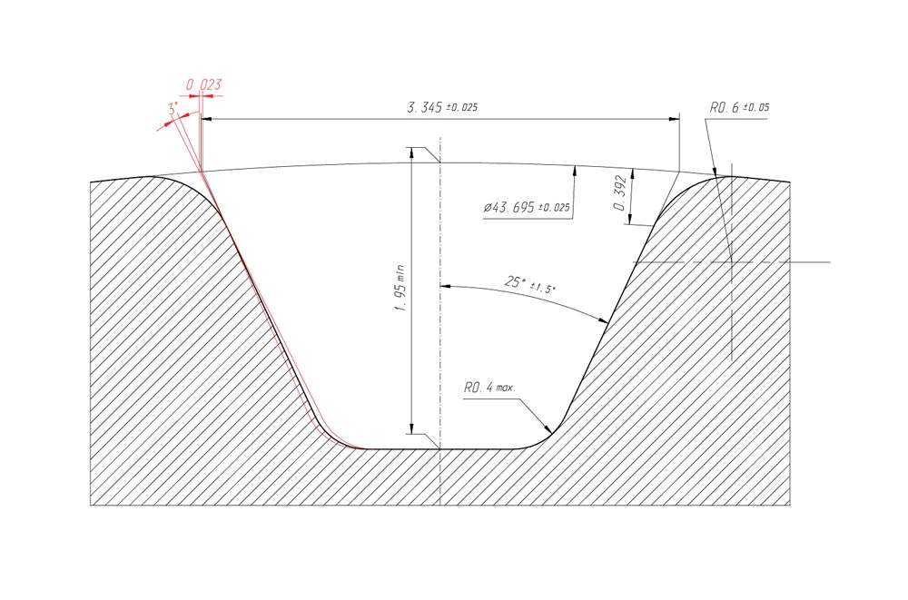
Figure 1—Geometry of a T5 28-tooth pulley.
The generating tool could machine the major diameter of the pulley. In such a case the tolerances on the major diameter would limit the possible positions of the generating tool. To keep the generating tool’s design as flexible as possible it has been assumed that the major diameter would be machined during the manufacture of the blank, and the generating tool would only machine the tooth gaps.
The tolerance of rounding R0.6 mm is specified two times wider than the tolerance of the major diameter, and the generating tool would machine this rounding. Even when the radius of rounding is kept within that tolerance, as the number of teeth generated on a pulley with a fixed reference profile changes, the radial height of rounding would also change. A generating tool could be designed to achieve a perfect transition of rounding into major diameter for one chosen number of teeth. Since different numbers of teeth are to be generated with that tool, it has been assumed in this paper that the radial height of rounding R0.6 mm (with a nominal value equal to 0.392 mm) must be monitored and maintained within the same tolerance as specified for the radius of rounding (±0.05 mm).
Reference Profile of Generating Tool
A reference profile of generating tool for a T5 28-tooth pulley has been obtained, using methods described in Refs. 2, 3, 4:
The local curvature of the reference profile at the point where rounding R0.6 ends and generating of flank begins is measured 8.68 mm, and the profile angle at that point is measured 21.06 degrees. When a small section of the profile is isolated, its deviation from a straight line is small enough to assume that it will shape an involute of a circle. In this study, a section with a length of 0.000536 mm (0.0005 mm high) has been used with a deviation from a straight line d calculated from Equation 1 as 4.1E-09 mm.
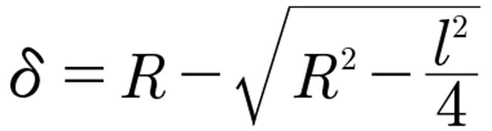
(1)
Calculating Parameters of Pulley Profile
The circular tooth thickness on pitch diameter for a 28-tooth pulley, generated with a reference profile shown on Figure 2, can be measured straight on the profile as no profile shift is required to achieve the required gap width of 3.345 mm. This circular tooth thickness is measured at 1.822 mm. When the number of teeth on the pulley is other than 28, the reference profile would also be different, but since the reference profile for 28 teeth will be used, profile shift needs to be applied to achieve the required gap width.
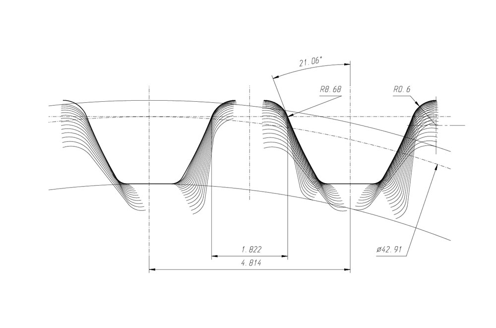
Figure 2—Reference profile of generating tool for a T5 28-tooth pulley.
(2)
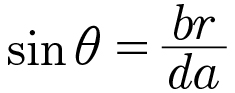
The circular gap width gr on diameter dx can be approximated from:

(3)
For 28 teeth, br=3.345 mm, da=43.695 mm, dx=42.91 mm and σ=25 degrees, the gr was calculated as 2.992912 mm. The angle θ is expressed in radians. The difference between gr calculated and measured in CAD is 0.0004 mm, which has been assumed to be accurate enough for the purposes of this study.
The calculating procedure begins with setting the number of teeth to be generated on the pulley. A small section on the reference profile, as shown in Figure 2, located where rounding R0.6 ends and flank begins, is generating the pulley’s profile at diameter dx. For this case study, the diameter dx was calculated using proprietary software (kzz) developed at Prozamet (Ref. 9). The same program was used for calculating the circular gap width on diameter dx, which was then compared with gr calculated from Equation 3. If these two are different, the gap width br is not equal to the specified value of 3.345 mm and the reference profile must be shifted to address that. The correct amount of reference profile shift was calculated with a modified Newton method. For a 25-tooth pulley, the calculated reference profile shift was –0.105 mm, and for a 30-tooth pulley it was +0.075 mm. The pulley’s profile flank angle σ was calculated from the slope of the generated section (Ref. 10).
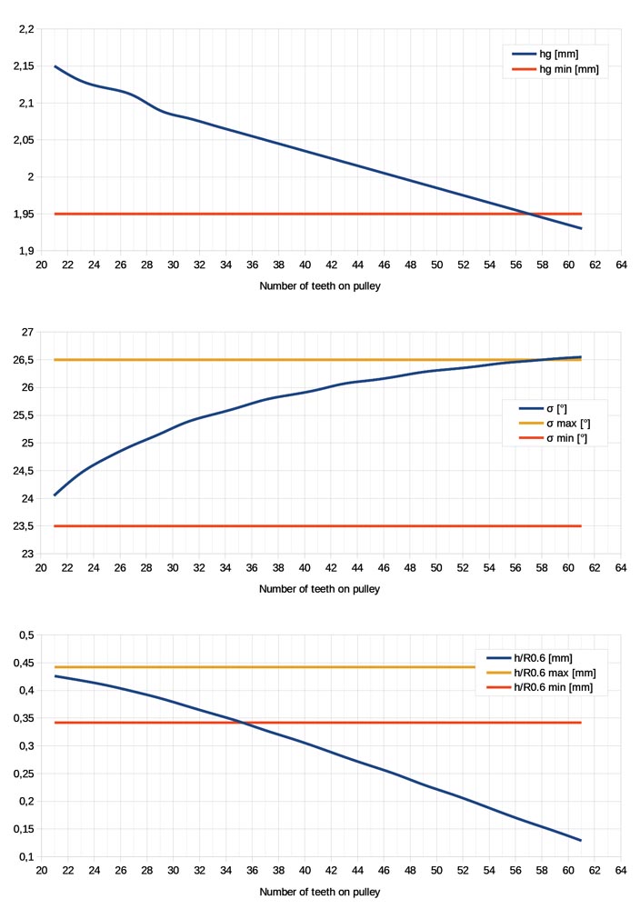
Figure 4—Application range charts.
Pulley Profile Parameters Calculated for 25, 28 and 30 Teeth
Table 1 shows the parameters of pulley profiles calculated for 25, 28, and 30 teeth. The profiles were generated with a reference profile for a 28-tooth pulley (Figure 2).
All parameters are within their respective tolerances—a reference profile for 28 teeth can generate 25 teeth and 30 teeth profiles.
Parameter | Symbol | Nominal value with tolerance | Generated with reference profile for a 28-tooth pulley | ||
Number of teeth | |||||
25 | 28 | 30 | |||
Major diameter | da | - | 38.925 mm | 43.695 mm | 46.885 mm |
Radial height of tooth | hg | 1.95 mm min | 2.12 mm | 2.10 mm | 2.09 mm |
Flank angle | σ | 25°±1°30’ | 24°44’ | 25°4’ | 25°17’ |
Radial height of rounding R0.6 | h/R0.6 | 0.392±0.05 mm | 0.409 mm | 0.392 mm | 0.378 mm |
The Range of Application of a T5 28-Tooth Reference Profile in the Generating of Pulleys with Different Numbers of Teeth
The method and criteria described above have been used to determine the range of application of T5 28-tooth reference profile in the generating of pulleys with different numbers of teeth. The smallest number of teeth is 21 because below that a different set of parameters is defined in the ISO standard. The results are shown on the Figure 4 charts.
The factor limiting the range of application is the radial height of rounding R0.6 mm. The 28-tooth reference profile can generate pulleys ranging from 21 to 35 teeth.
Conclusion
In the process of modeling the T5 pulley profiles in accordance with ISO 17396:2017, some definitions in that standard were interpreted to derive applicable validation criteria of the geometrical parameters of profiles. An analytical method for reference profile evaluation was developed to address problems with previously used methods, which were based on manual comparisons of profiles in CAD software. It might be surprising that the critical factor, most severely limiting the application range of a reference profile, turns out to be the radial height of the tooth tip’s rounding R0.6 (h/R0.6). Has that limitation been recognized and introduced intentionally, or should a revision of rounding tolerances be considered?

References
- ISO 17396:2017, Synchronous belt drives—Metric pitch—Tooth profiles T and AT endless and open-ended belts and pulleys.
- Nieszporek, T. (2004), Fundamentals of construction of cutting tools for machining cylindrical external gearing. Publishing House of the Częstochowa University of Technology.
- Sobolewski, B. and Marciniec, A. (2013), Method of spiral bevel gear tooth contact analysis performed in CAD environment, Aircraft Engineering and Aerospace Technology, Vol. 85, No. 6, pp. 467–474.
- Sałaciński, T. (2005), “Simulation of flank bevel gears shaping and verification.” Polish Academy of Sciences. Machine Building Committee, Z. Machine Operation Issues, Vol. 40, No. 2 Vol., pp. 169–178.
- Perneder, R. (2009), Toothed belt technology handbook. Basics, calculation, applications, Springer-Verlag Berlin Heidelberg.
- PWS Precision Tools GmbH, Product Catalog No. 7091, 7093, PWSN 7.056 hobs for toothed belt pulleys.
- Edimodul Ltd, Hobs for gear belt pulley with spacing in mm according to DIN 7721. Available at: https://www.edimodul.hu/en/hobs-for-gear-belt-pulley/hobs-for-gear-belt-pulley-with-spacing-in-mm-according-to-din-7721.html (Accessed: 13 March 2023).
- Ash Gear & Supply Inc. (2000), Catalog. Also available at: http://ashgear.com/pdfs/htx.pdf (Accessed: 13 March 2023).
- Prozamet is a company based in Poland that manufactures gears and gear units.
- Slope of a Line (2011). Available at: https://www.mathopenref.com/coordslope.html (Accessed: 13 March 2023).