
Force Modeling in Generating Gear Grinding Considering the Grinding Worm Topography
Introduction
Continuous generating gear grinding is a hard finishing process mainly used to meet the high requirements for gears in terms of geometry and surface quality (Ref. 1). During grinding, a major percentage of the generated energy is converted into heat. Depending on the process conditions, a fraction of 60–90 percent of the generated heat can flow into the workpiece (Ref. 2). This fraction of generated heat leads to high temperatures in the contact zone, which can cause thermal damage in the workpiece (Refs. 3,4,5).
To better understand and control the part of the generated heat that flows into the workpiece, it is first necessary to specify the according energy partition. In the work of Hahn, it was established that the removal of material by each grain of the grinding tool during the process is performed based on three different mechanisms: friction, plowing, and shearing (Ref. 6). Each of these mechanisms contributes to the partition of energy that goes into the workpiece in a singular way (Ref. 4).
The grain energy generated in each of the three phases of material removal depends on grain-workpiece microinteraction characteristics such as grain contact length, grain penetration depth, and grain cross-section area (Ref. 2). These microinteraction characteristics are significantly influenced by the grinding tool topography and the grains interacting with the material (Ref. 7). In turn, the interaction of the grains of the grinding wheel topography with the gear is characterized based on both process kinematics and process parameters. To develop a suitable grinding energy calculation for generating gear grinding, it is necessary to consider how each grain interacts in the contact zone, based on the process parameters to which they are submitted.
For the research developed in this work, an existing simulation model of the generating gear grinding process based on a penetration calculation approach is used. Further, an extension of the model considering a realistic modeling of the grinding worm topography and the macro movements of the grinding worm during the process is presented. The result of the simulation is the microinteraction characteristics throughout the grinding of the gear flank. In the end, the information about microinteraction characteristics obtained will be used for the calculation of force and energy in generating gear grinding.
State of the Art
Generating gear grinding is one of the most efficient processes for hard finishing of gears. In the process, the cylindrical grinding worm whose profile equates to a rack profile in a transverse section meshes with an external gear (Ref. 1). The involute of the gear is generated by the continuous generating motion of the grinding worm and workpiece by the profile cuts method. One special characteristic of the process is the multiple points of contact between the grinding worm and the gear, Fig. 1. The number of contact points changes continuously during the tool rotation (Ref. 1).
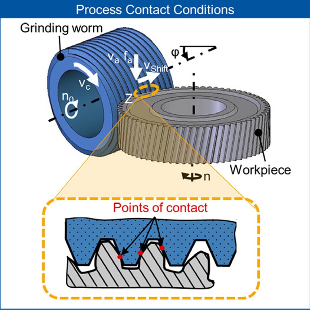
Figure 1—Generating gear grinding process.
Based on the grinding worm topography, process parameters, and process kinematics, the microinteraction characteristics are different for each grain. Ultimately, these differences influence the force and the energy in the contact zone. To predict the force and energy of the process, simulation models have been developed in the last years, considering the complex kinematics of generating gear grinding as well as the microinteraction characteristics (Refs. 8, 9, 10). One of these simulation models will be reviewed in the next section. Furthermore, a review of the microinteraction characteristics currently considered in the software for the calculation of the forces is performed. In addition, the calculation of the energy for generating gear grinding considering the microinteraction characteristics is described and reviewed.
Modeling for Generating Gear Grinding
Modeling of manufacturing processes can be done by means of a penetration calculation approach. In a penetration calculation, characteristic process values can be calculated considering the kinematics and geometry of the workpiece and tool. A three-dimensional model is simplified to a two-dimensional model by means of sectional planes. In the work of Brecher et al., a simulation model is described (Ref. 9), Figure 2.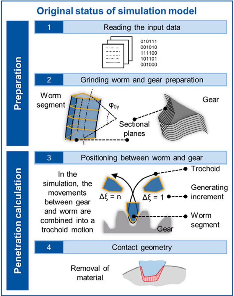
Figure 2—Steps for the simulation model.
The simulation is performed in several steps. In the first step, input data such as gear and tool geometry and process parameters are read. Next, models of the grinding worm and the pre-cut gear based on sectional planes are generated. The sectional planes in the grinding worm represent the tool profile. To keep the computational effort as low as possible, only a segment of the actual grinding worm is considered for the simulation, defined by an opening angle of φ0y, middle of Figure 2. In the next step, an abstraction of the actual process kinematics was introduced in the simulation model, to decrease the complexity of the modeling. In the abstracted kinematics, the grinding worm segment is positioned relatively to the gear, following a trochoid curve. The trochoid-generating motion of the grinding worm of the simulation model represents a combination between the movements of the gear and tool, occurring in the real process. Despite the kinematics abstraction, the same contact conditions and material removal to the real process are achieved in the end of the simulation. The trochoid-generating motion is discretized along the process by a defined generating increment Δξ. Between the first and the last generating increment Δξ, a complete machining of the tooth gap’s sectional planes is performed. The contact geometry between the grinding worm segment and the gear is calculated for all discrete generating positions, in the lower middle of Figure 2.
Now, the simulation model only considers the macro interaction of the tool and the gear. However, for an accurate energy and force calculation, the microinteractions between the grinding worm and the gear are also of high relevance. The abstraction of the process kinematics used in the simulation model, without an accurate representation of the tool rotation and the cutting speed, makes modeling of microinteractions not possible. The rotational movement of the tool surface has a significant influence on the grinding worm topography interaction with the material. The rotational movement is essential for the generation of the path of contact between grains and gear during the process, and it cannot be neglected in the simulation if the microinteractions should be analyzed.
Microinteraction Characteristics in Generating Gear Grinding
In the work of Hübner, an investigation of the normal force calculation considering the engagement of the grains with the help of the simulation model (see “Modeling for Generating Gear Grinding”) was performed (Ref. 12). In his work, the normal force model developed by Werner was transferred to generating gear grinding (Ref. 13), see equation shown in the upper of Figure 3. Except for the specific force k, all the variables were calculated in the simulation model. In the work of Hübner, the grinding worm topography was modeled by means of measured 2D contours of individual grains. Those individual grains were subsequently mapped onto the grinding tool profile manually. While this approach can be suitable for monolayer galvanic grinding tools, the irregularities of the grain distribution of vitrified grinding worms are not reproduced accurately. Therefore, the approach used by Hübner, did not consider two important factors of the grinding worm topography. The first factor is the different protuberance of the grains from the grinding worm topography, which leads to the situation where not all the grains from the grinding worm topography are in contact with the workpiece. The second factor is the shadowing effect during the contact between the workpiece and the grinding worm. The shadowing effect characterizes the influence of the first grains in contact with the material on the engagement of the grains which are in contact with the material immediately afterward.
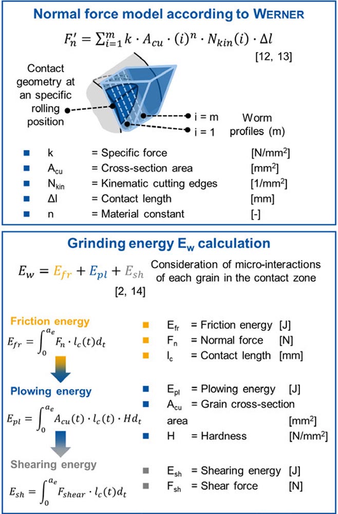
Figure 3—Calculation of force and energy for generating gear grinding process from previous research.
The process energy Ew corresponds to the energy required to remove material and is commonly assumed to be equal to the spindle energy (Ref. 2). In the previous work of Teixeira, an energy model considering the chip formation mechanisms of the engagement of one single grain for generating grinding was proposed (Refs. 14, 15). This model was based on the work of Linke, where the energy of each chip formation mechanism was calculated differently, considering its specific aspects for the process of surface grinding (Ref. 2). In the model of Teixeira, the work of Linke was expanded for the process of generating gear grinding, upper right of Figure 3, and single-grain trials were performed for validation. A more detailed description of the calculation method for the energy of each chip formation mechanism can be found in (Ref. 14).
For the calculation of the energy of each chip formation mechanism, information regarding the microinteraction characteristics of the grains, such as contact length lc, grain cross-section area Ac and chip thickness hc are required. In the end, the process energy Ew was calculated as the sum of all the energies from each chip formation mechanism, of all the grains engaging in the material, upper right of Figure 3. Even though different research has been performed on the topic of simulation models for force and energy for generating gear grinding, an investigation of the microinteraction characteristics using more realistic modeling of the grinding worm topography while considering the complex kinematics and tool rotation movement of the process is required The consideration of tool topography and grinding worm rotation will enable a more detailed calculation of the energy for generating gear grinding process.
Objective and Approach
Based on the scientific gap in the simulation model explained in “State of the Art” regarding the consideration of grinding worm topography and tool rotational movement, the objective of this work is defined. The main objective of the work is the development of a force and energy model for generating gear grinding considering the process kinematics and the microinteraction of grinding worm topography and gear.
Extension of Simulation Model Considering the Tool Topography
In this section, the extensions implemented in the simulation model are described. There are two different types of extensions to be performed: (1) grinding worm topography and (2) grinding worm rotational movement. The implementation of the grinding worm topography in the simulation model is first described, Figure 4.
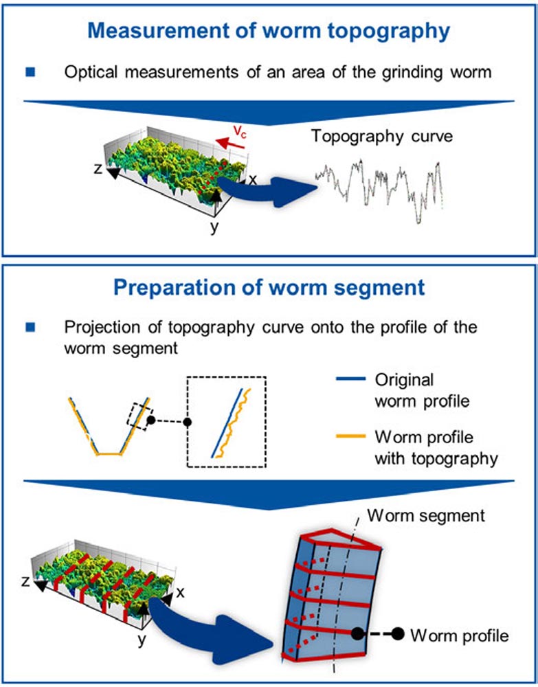
Figure 4—Extension of simulation model regarding grinding worm topography.
The first step is an optical measurement of the grinding worm topography with a laser scanning microscope. The measurement is performed with a resolution of 20x, in an area of the grinding worm large enough for a representative sample of the entire grinding worm specification. The optical measurement is analyzed with the support of the software MountainsMap. In the software MoutainsMap, topography curves are extracted in several positions along the z-axis, Figure 4. Next, the topography curve is brought onto the worm segment. The worm segment, shown at the bottom of Figure 4, is formed by sectional planes called tool profiles. Each topography curve of the real grinding worm is projected onto one different tool profile. In the end, the topography of the real grinding worm will be represented in the worm segment used in the simulation model.
The second extension required in the simulation model is regarding the grinding worm rotational movement. The worm segment is positioned relative to the gear following a trochoid motion. In the original version of the simulation model, the position of the worm segment changes along the simulation, but the worm segment itself does not change or rotate. In addition, all the tool profiles of the worm segment are the same. In the extended simulation model, each tool profile from the worm segment has a different topography curve. The rotational movement of the worm segment is implemented by a change in the position of each tool profile during the simulation, see Figure 5.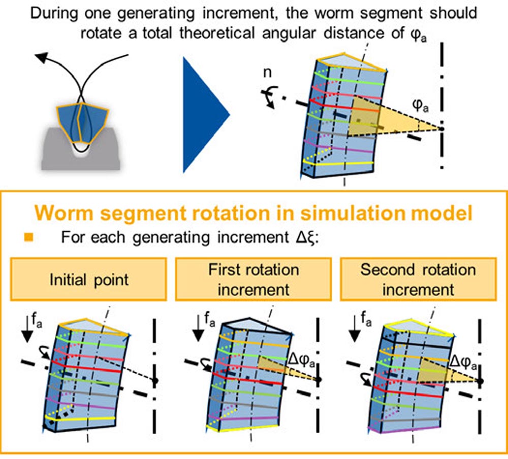
Figure 5—Extension of simulation model regarding grinding worm rotational movement.
The changes in the position of the tool profiles are correlated to the process parameters and the generating increment Δξ. During one generating increment Δξ, the worm segment should rotate a total theoretical angular distance of φa. Based on the theoretical angular distance φa, the number of times the position of tool profiles has to be changed is defined. The change of position of the tool profiles is conducted by single rotation increments until the theoretical angular distance φa is reached. After the angular φa distance is reached, the simulation continues to the next generating increment Δξ, and the procedure for the change of position of the tool profiles is repeated within the new generating increment. With this procedure, the simulation model was extended in terms of a realistic consideration of the grinding worm topography as well as the rotational movement.
Analysis of Results
In this section, the calculation of force and energy for the process of generating gear grinding based on the microinteraction characteristics of the grains engaging with the gear material is performed and discussed.
Verification of Extension of Simulation Model
After the extension of the simulation model, the microinteraction characteristics of all the grains engaging with the gear during the process are obtained. With the microinteraction characteristics from the simulation model, the normal force Fn for generating gear grinding is calculated, based on the model of Werner (see Figure 3) (Ref. 13). To verify if the microinteraction characteristics used for the force calculation are suitable, the normal force Fn calculated in this work is compared to the results from the model developed by Hübner, which was already validated by means of experimental trials (Ref. 12). A simulation with the extended simulation model is performed, with the same parameters used in the work of Hübner (Ref. 12). The diagrams in the lower part of Figure 6 show the normal force Fn calculated in the work of Hübner, upper diagram, and the normal force Fn calculated using the model in the current work, lower diagram.
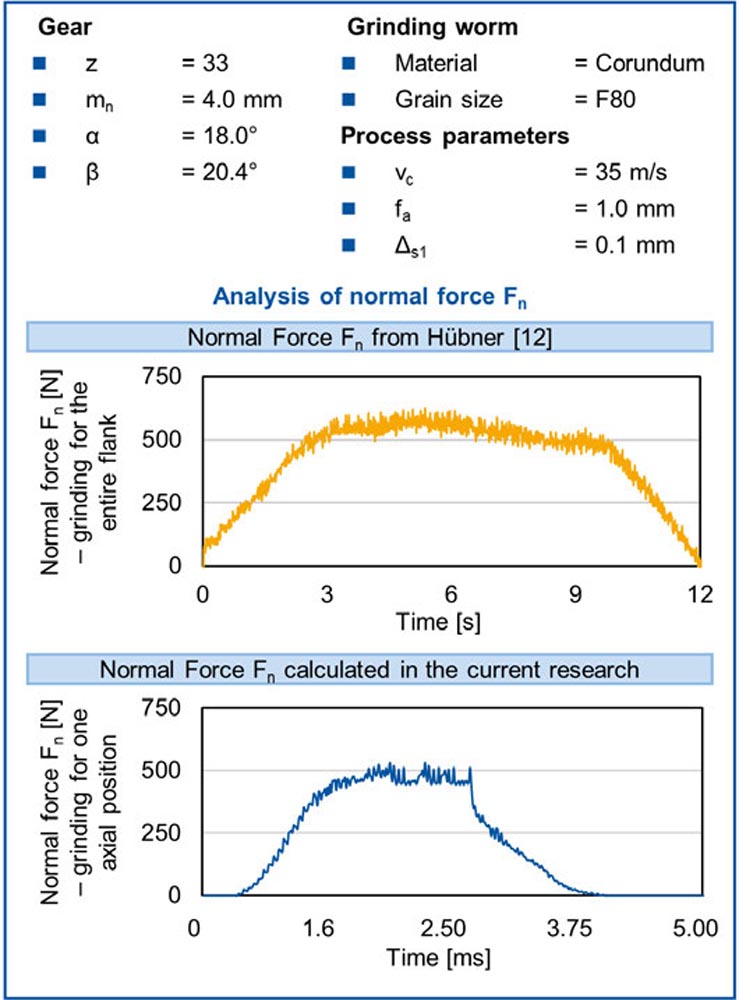
Figure 6—Analysis of the generating gear grinding normal force calculation.
In the simulation model, a type of simulation called fast simulation is possible. In this type of simulation, only one area in the middle of the gear flank is considered, where full contact between tool and gear occurs. The simulation represents only one axial position of the gear gap and only the maximum values of the process characteristic values are calculated. In his work, Hübner was able to validate the normal force Fn calculated by means of experimental trials. The diagram shows the normal force Fn calculated by Hübner, during the grinding of a gap in the entire flank. The next diagram shows the normal force Fn calculated in the current work, during the grinding of a gap in only one axial position.
A comparison between the normal force obtained by the extended simulation model and the model developed by Hübner shows good accordance. It is possible to assume that the microinteraction characteristics calculated by the extended simulation model are in accordance with the real process.
Energy Calculation Method for Generating Gear Grinding Process
The process energy Ew is calculated based on the sum of the energies induced by each of the three chip formation mechanisms along the grain engagement (see Figure 3). For the analysis of the calculated process energy Ew, a simulation is performed. The gear, grinding worm, and process parameters used in the simulation are the same ones used in the simulation described in “Verification of Extension of Simulation Model.” In the upper side of Figure 7, the process energy Ew resulting from the simulation is shown.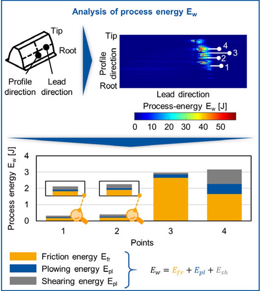
Figure 7—Analysis of the process energy calculation for generating gear grinding.
In the image of the process energy Ew plotted on the gear flank, the upper side of Figure 7, four points are randomly chosen at the area of contact between gear and tool are highlighted. In these four points, a further analysis of the energy was performed. In the diagram, it is possible to see the contribution of each individual energy of each chip formation mechanism to the process energy Ew. For points one and two, similar process energies and contributions are obtained. Regarding points three and four, the process energies Ew are also like each other, but the contributions of each individual energy of each chip formation mechanism are different. The friction energy Efr is responsible for the highest contribution to the process energy Ew, in all four points analyzed. The contribution of the plowing energy Epl is slightly smaller than both friction Efr and shearing Esh energy for all points except for point three. For point three, the plowing energy Epl is greater than the shearing energy Esh.
Each of these chip formation mechanisms has a different contribution to the heat transferred into the gear. Almost all the friction energy Efr is conducted as heat to the workpiece, while for plowing Epl and shearing Esh energies, this fraction is smaller (Ref. 4). The fraction of energy conducted as heat to the workpiece for the shearing mechanism is the lowest of the three mechanisms. Therefore, most of this energy is used for chip removal and not to heat the workpiece. If most of the process energy is not converted to heat, the possibility of grinding burn during the process decreases.
Due to this, even though points three and four presented similar process energies Ew, the contribution of each individual energy of each chip formation mechanism is different for each of these points, leading to different amounts of heat transferred into the workpiece.
Conclusions
To achieve the objective defined, an extension of a simulation model focused on the implementation of the grinding worm topography and its rotational movement was performed. Based on the microinteraction characteristics calculated in the extended simulation, the normal force of the process was calculated, and it showed good agreement with the literature. Hence, the extended model was verified against an experimentally validated model. The process energy Ew was calculated as the sum of all the energies of each chip formation mechanism, for all the grains engaging in the material. The energy of each chip formation mechanism contributes differently to the total energy partition and conduction of heat to the workpiece. Therefore, the extended simulation model allows us to understand how much of the energy generated during the process can be conducted as heat to the workpiece. Ultimately, this can be used to avoid grinding burn in the process of generating gear grinding. As an outlook, validation by means of grinding trials is planned. Critical values of process energy Ew and the influence of each chip formation mechanism energy on the grinding burn presence need to be defined. In addition, to avoid the time-consuming task of measuring the grinding worm topography optically, a routine for generating a generic random grinding worm topography as input for the simulation will be implemented soon.
Acknowledgments
Funded by the Deutsche Forschungsgemeinschaft (DFG, German Research Foundation) under Germany’s Excellence Strategy—EXC-2023 Internet of Production—390621612.

References
1.Ophey, M.: Modellierung des Schleifschneckenprofilverschleißes beim kontinuierlichen Wälzschleifen. Diss. RWTH Aachen University, 2019.
2.Linke, B.; Garretson, I; Torner, F.; Seewig, J.: Grinding Energy Modeling Based on Friction, Plowing, and Shearing. In: Journal of Manufacturing Science and Engineering, 139, 2017, S. 1–11.
3.Malkin, S.: Grinding Technology: Theory and Applications of Machining with Abrasives. Oxford, Society of Manufacturing Engineers, 1989.
4.Malkin, S.; Guo, C.: Thermal Analysis of Grinding. In: CIRP Ann., 56. Jg., 2007, Nr. 2, S. 760–782.
5.Langenhorst, L.; Borchers, F.; Heinzel, C.: Analysis of internal material loads and resulting modifications for grinding with mechanical main impact. In 8th CIRP Conference on High Performance Cutting, 2018, S. 533-536.
6.Hahn, E.R.: On the Mechanis of the Grinding Process under Plunge Cut Conditions. In Journal of Engineering for Industry, 1966, S. 72-80.
7.Palmer, J.; Curtis, D.; Novovic, D.; Ghadbeigi, H.: The influence of abrasive grit morphology on wheel topography and grinding performance. In 8th CIRP Conference on High Performance Cutting, 2018, S. 239-242.
8.Haifeng, C.; Jinyuan, T.; Wei, Z.: Modeling and predicting of surface roughness for generating grinding gear. In Journal of Materials Processing Technology, 2013, S. 717-721.
9.Kadivar, M.; Azarhoushang, B.; Krajnik, P.: Modeling of micro-grinding forces considering dressing parameters and tool deflection. In Precision Engineering, 2021, S. 269-281.
10. Brecher, C.; Klocke, F.; Löpenhaus, C.; Hübner, F.: Analysis of abrasive grit cutting for generating gear grinding. In: 10th CIRP Conference on Intelligent Computation in Manufacturing Engineering 62 (2017), S. 299-304.
11. Mazak, J.: Methode zur Fertigungssimulation von Kegelrädern basierend auf einer zweidimensionalen Durchdringungsrechnung. Masterarbeit RWTH Aachen University, 2014.
12. Hübner, F.; Löpenhaus, C.; Klocke, F.; Brecher, C.: Analysis of abrasive grit cutting for generating gear grinding. In: 10th CIRP Conference on Intelligent Computation in Manufacturing Engineering, 2016.
13. Werner, G.: Kinematik und Mechanik des Schleifprozesses. Diss. RWTH Aachen University, 1971
14. Teixeira, P.H.O.: Energy modelling for generating gear grinding considering the chip formation mechanisms. In 61th Conference “Gear and Transmission Research” of the WZL, Aachen, Germany. 2020.
15. Teixeira, P.H.O.: Consideration of Micro-Interaction in the Modeling of Generating Gear Grinding Processes. In 62nd Conference “Gear and Transmission Research” of the WZL, Aachen, Germany. 2022.
This paper was first presented at the 9th WZL Gear Conference in the USA, held July 2022 in Itasca, IL. It is reprinted here with permission. |