
Test Rig for Crowned Spline Joints with Optimized Surface Treatments Under Misaligned Conditions
In powertrain technology, spline couplings are used to connect gears and shafts in order to transmit high torque (Ref. 1). Furthermore, spline couplings are used in modern gas turbine aero engines to connect shaft systems and compensate shaft misalignments (Ref. 2). The compensation for shaft misalignments leads to a reduction of the constraining forces affecting surrounding machine parts (Ref. 3). While considering a load reduction based on the reduced constraining forces, the design engineer is able to reduce the required packaging volume and components weight of the whole system. Overall, this can be used to cut manufacturing costs because of a material reduction and to improve the system efficiency and simultaneously decrease the system emissions due to reduced inertia (Ref. 4).
As shown, the specific compensation for shaft misalignments with spline couplings can lead to different benefits in powertrain applications. On the downside, a growing misalignment inside of the spline coupling leads to growing sliding velocities that raise the risk of upcoming wear and fatigue phenomena on the tooth flanks (Ref. 5). Whether damages related to wear and fatigue occur is determined by the ratio between the prevailing stress and the load-carrying capacity. While increasing the stress throughout growing sliding velocities, it must be ensured that the load-carrying capacity is not exceeded. Factors influencing the load-carrying capacity of crowned spline joints include the material and heat treatment, the manufacturing history and single manufacturing steps, the final surface properties as well as the prevailing boundary conditions during operation, such as lubrication and temperature. Going further, recent research is carried out to minimize the wear effects in crowned spline joints throughout the development of surface treatments, such as PVD-coating and laser-structuring (Ref. 6).
Overall, the demands on the load-carrying capacity increase when spline joints are used for the compensation for shaft misalignments. To enable safe operation while excluding over-dimensioning, a detailed knowledge and understanding of the influencing factors on the load-carrying capacity of crowned spline joints under misaligned conditions is necessary. To investigate and evaluate the influencing factors and the performance of new surface treatments for crowned spline joints, component tests under high rotational speed and torque within misaligned shafts must be carried out. Looking at an exemplary application of spline joints in gas turbine aero engines, component testing in the application is not suitable for research investigations. To obtain time-efficient and economic test results, a sufficient test rig is essential. This paper aims to identify and summarize existing possibilities of spline-joint test rigs in literature and present a new test rig, designed for the investigation of crowned spline-joints under misaligned conditions, high rotational speed, and torque within misaligned conditions.
State-of-the-Art Analysis
Spline couplings loaded with cyclic strains are susceptible to plain fatigue, fretting fatigue, and fretting wear (Ref. 2). Investigations according to these spline-joint phenomena are mostly carried out on test rig concepts that can be divided into three categories:
- Analogy Tests with Simple Specimens
- Analogy Tests with Spline Joints
- Spline-Joint Tests Under Real Working Conditions
Following, different test rig setups are introduced to outline the state-of-the-art knowledge for the investigation of wear phenomena, which appear in loaded spline-joint connections, see Figure 1.
I. Analogy Tests with Simple Specimens
Limmer et al. state that the use of inline hydraulic test machines, such as linear actuators, is an efficient way to cut specimen-manufacturing costs compared to the testing of full-scale splines. Describing an assembly of a static specimen that is clamped between two fretting pads, which are moved up and down, the appearing contact conditions in running spline joints were reproduced, see Figure 1. While using a pulsating actuator for the fretting pad movement, the test time was reduced due to the possible high load frequencies (Ref. 7).
Ferre et al. additionally applied a normal load between simple-plane and cylindrical fretting pads. Combined with the load of a pulsator, that created a cyclic displacement amplitude, fretting fatigue was investigated (Ref. 8).
Also applying a normal load and a displacement amplitude, Hyde et al. and Leen et al. used representative spline specimens, with simplified tooth flanks to reproduce the frictional contact in spline joints for their fretting investigations (Refs. 9, 10).
Wavish et al. went further and combined a low-frequency in-plane cyclic normal clamping load and a higher-frequency out-of-plane cyclic fatigue stress. This enabled fretting investigations by superimposing multiaxial fretting conditions (Ref. 11).
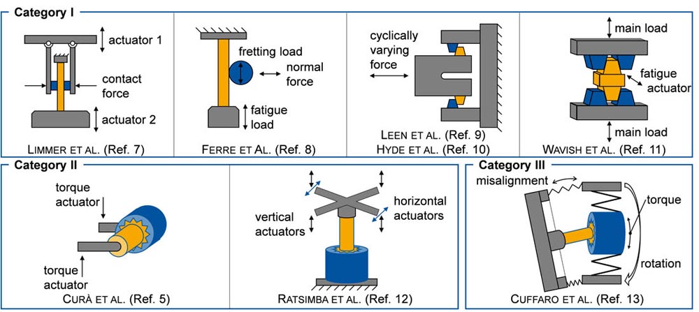
Figure 1—State of the art: test-rig setups for the investigation of wear phenomena in spline joints (Refs. 5, 7, 8, 9, 10, 11, 12, 13).
II. Analogy Tests with Spline Joints
Curà et al. used a pulsator with a torque-generating lever device for spline-joint testing. By means of this device, component tests with variable torque amplitudes could be proceeded. Throughout the use of the Pulsator, time-efficient testing was realized (Ref. 5).
Ratsimba et al. investigated fatigue failure and fretting wear on a spline-joint test setup with multiple actuators to reproduce multiaxial loads. While testing a vertically clamped spline coupling, the torque was generated by two horizontal actuators, which were mounted on two opposing levers. Additionally, four vertical actuators in combination with a crossed lever system were mounted to the spline shaft. By means of this setup, axial loads and rotating bending forces appearing in spline joints under misaligned shaft conditions were reproduced and could be tested economically (Ref. 12).
On the one hand, analogy tests with spline joints enable resource and time-efficient testing, by using pulsating actuators and torque-generating lever devices. On the other hand, the use of these actuators instead of rotating spline joints, results in the neglection of the axial pressure peak movement associated with misaligned spline joints. Therefore, different contact patterns according to each single flank are generated. Additionally, the prevailing flow of the lubricant in the tooth mesh is not properly reproduced. Due to the missing centrifugal forces and radial conveyance effects because of the movement of the contact zone, the lubrication conditions in the analogy tests differ from real applications.
III. Spline-Joint Tests Under Real Working Conditions
Testing spline joints under real working conditions requires a more extensive test rig setup to properly account for the load case, including the rotational speed, torsional load, and dedicated shaft misalignment. Cuffaro et al. presented a spline coupling test rig fulfilling these requirements by installing a split coaxial shaft system with mechanical power recirculation. For this purpose, the two parts consisting of each one inner and one outer shaft were connected. The inner shafts were connected with the tested spline joint and the outer shafts by a flexible joint. While rotating this shaft system, pretensioned with the test torque, the spline joint ran under more realistic working conditions. For tests under misaligned conditions, the two parts of the shaft system could be tilted against each other along the axis of the spline parts. With this test setup a maximum torque of Tmax = 5000 Nm and a maximum rotational speed of nmax = 2000 rpm could be provided for spline testing with a maximum temperature of ϑmax = 60°C. Related to these operating specifications, the performance characteristic of the test rig presented by Cuffaro et al. aims at high torque applications under lower rotational speed (Ref. 13).
Conclusion on the State of the Art
As shown, the majority of spline coupling test rigs entrenched in literature were built up as analogy test rigs. Analogy test rigs with simple specimens reproduce a sliding condition between test specimens under contact pressure to reproduce the contact properties prevailing in loaded spline joints. On the one hand, the benefits of testing on analogy test rigs with simple specimens is that the specimen manufacturing is cost-efficient, and the testing time is short since pulsating actuators with high test frequencies are used. This enables statistical testing in a reasonable time and cost frame. On the other hand, the major disadvantage of analogy test rigs is that the prevailing working conditions of the application are not completely reproduced. Especially when spline joints are operated under angular misalignments of the shaft systems, the specific kinematics of the tooth contact is not sufficiently replicated by analogy test rigs even if they use spline joints as test specimens. Finally, the axial movement of the contact zone over the tooth flank cannot be reproduced on the existing analogy test rigs. To fully examine occurring damage mechanisms and wear phenomena of misaligned spline joints, it is necessary to test spline joints under real working conditions. A test rig that can be used for this purpose is described by Cuffaro et al., which focuses on high torque, lower rotational speed, and moderate temperature testing. However, high rotational speeds and high test temperatures are prevalent in modern gas turbine aero engines, so there is a deficit in the capability to test spline joints under application near test conditions. Therefore, the objective of this paper is to present a newly developed test rig and a test spline geometry for high rotational speed and high-temperature testing of crowned spline joints under misaligned conditions. For this purpose, a back-to-back test rig is enlarged by multiple features to test misaligned spline joints inside the power recirculation circuit of the test rig. Besides high rotational speed, high test temperatures up to a maximum of ϑmax = 120°C are realized by a controlled oil injection into the tooth mesh.
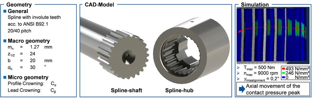
Figure 2—Test spline joint design.
Design of a Test Spline Joint
For the investigation of wear phenomena of misaligned spline joints under real working conditions with a performance characteristic of high rotational speed, medium torque, and high operating temperatures, a full-scale spline joint and a test rig were designed. The design of the test spline geometry is presented for a working, crowned, side fit spline-joint, see Figure 2. In the design process, the focus was to generate the same contact conditions, which prevail in the tooth flank contact of spline joints in aircraft-engine gas turbines. To enable testing on existing test rigs, the size of the test spline was reduced in comparison to the application. To ensure that the prevailing contact conditions resemble the contact conditions of the application, the contact pressure and the ratio of the sliding velocities were used as design parameters.
Considering the target value for the contact pressure, the spline macrogeometry was designed according to ANSI B92.1 to fit a test torque that matches the common load levels of a back-to-back test rig (Ref. 14). Additionally, the spline microgeometry and the dedicated shaft misalignment γmisalignment were designed to further fit the kinematics of the application. Therefore, a FEM simulation of the spline connection was carried out. In the operation of loaded, misaligned spline joints, the maximum pressure peaks move cyclically on each rotation axially along the tooth flanks. While analyzing the static contact zone distribution over all teeth, the displacement of the contact zone over the angular positions of the single teeth was recorded, see Figure 2. With this data and the rotational speed, the kinematics of the contact movement was calculated. The contact zone movement can be described by a cyclic sliding velocity function. For the calculation of the movement of the contact zone, not only does the rotational speed and the distance between the contact zones need to be considered, but also the sine relation of the sliding velocity function must be considered. To calculate the maximum local sliding velocity as well as the maximum global sliding velocity, the sine-dependent nonlinearity of the sliding velocity function was evaluated. Based on this calculation, the spline design was finalized to generate a tooth mesh characteristic with the dedicated contact pressure and maximum axial sliding velocity.
In the next step, to assess the capabilities of newly developed surface treatments, spline joints for the tests were manufactured. The designed spline geometry was processed out of the nitriding steel 32CDV13, which is widely used in aerospace applications. This material was chosen to meet the application of an aircraft-engine gas turbine. For the manufacturing, the process chain followed a conventional gear manufacturing process route for nitriding steels, see Figure 3.
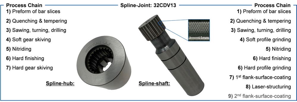
Figure 3—Test-spline joint: process chain.
After quenching and tempering the preforms, the blanks were machined, followed by soft machining of the gear. Next, the specimens were plasma-nitrided and then the functional surfaces and the gears were hard-finished. For the gear manufacturing steps, a gear-skiving process was carried out for the soft- and hard-machining of the spline hubs and a discontinuous profile grinding process for the spline shafts. Then, the different surface optimizations were applied. For this purpose, the coating and structuring systems described by Stephen et al. were used (Ref. 15). Two different variants were manufactured in terms of physical vapor deposition (PVD) to generate TiN + MoS2:Ti and TiN + DLC + MoS:Ti:C multilayered coatings. Additionally, a laser structuring process took place, where dimples with diameters between dstruct = 40 to 80 µm were applied on the tooth flanks, as shown in Figure 3. Finally, a second coating step took place for selected test variants to apply a solid lubrication layer.
In the next step, the presented spline joints will be tested according to their wear behavior under misaligned conditions. To realize reproducible test conditions within a time-and-cost-based economic framework, a suitable test rig for the planned investigations is presented.
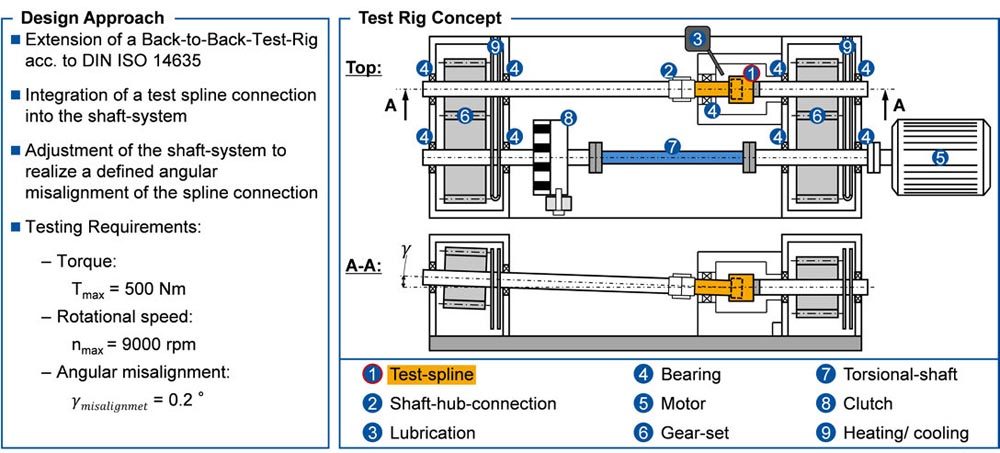
Figure 4—Test rig concept.
3 Test Rig Design
A common method in gear load capacity testing is to use power recirculation for the test power generation. The idea behind this approach is to apply and entrap a static torque in a power circuit through pretensioned spring elements. A motor then drives this power circuit (Ref. 16). Due to the entrapped static test torque, the motor only needs to overcome the power dissipation of the system but not the actual test power. This leads to an economical test rig design since only the power dissipation of the system must be applied during endurance testing, rather than the high power, which is transmitted by the test gears. A test rig that features a power circuit and is widely used for this testing is the back-to-back test rig, standardized by DIN ISO 14635 (Ref. 17). This test rig is built to investigate cylindrical gears. Following, the extension of a back-to-back test rig is presented, which enables the testing of spline joints, see Figure 4. Based on the test spline geometry and the targeted contact pressure and contact kinematics for spline-joint testing, the following test rig requirements were implemented:
| – Test torque: | Tmax = 500 Nm |
| – Rotational speed: | nmax = 9000 rpm |
| – Dedicated shaft misalignment: | γmisalignment = 0.2° |
To match the performance range of the presented test spline-joint, a back-to-back test rig with a center distance of a = 112.5 mm was used. For the testing, the spline joint was integrated into the power circuit of the test rig. Therefore, the shaft system of the standard setup was reconfigured. On the motor averted side, the clutch was removed to gain space for the test spline. An axial slim clutch and the torsional shaft were applied in the shaft system on the motor side. On the motor averted side, a new bearing system was applied since the rotational speed for the testing of the spline-joints nmax = 9000 rpm exceeds the speed spectrum of the standard setup. Going further, two new shafts were designed for this side to integrate the spline joint into the power circuit. The test spline hub was directly mounted and clamped onto the right-hand side test shaft. Due to the mountability, the spline shaft was attached to the left-hand side shaft with hydraulic-shaft hub connections, which can be removed during assembly. To additionally stabilize the spline joint, a support bearing was attached to the spline shaft and the housing. The housing shields the spline joint during the test run, seals the test space against oil leakage, and enables a consistent test temperature.
To generate the dedicated spline-joint misalignment of γmisalignment = 0.2 degrees the left-hand side of the motor averted shaft system, including the spline shaft, was tilted upwards around the center of the spline joint, see Figure 4. Therefore, special bearing bushes were designed. The bearing seats of the left-hand side shaft system were aligned with the necessary deviation from the axis of the right-hand side shaft to generate the dedicated spline misalignment. To gain high precision for the manufacturing of the bearing seats, the final processing was done in a single clamping. With this procedure, the angular spline misalignment is fixed for the assembly. To change the dedicated misalignment, it is necessary to change the bearing bushes. The benefit of this design is, that the misalignment is fixed for the assembly and therefore remains the same for all tests of a test series. Going further, two cylindrical gear sets were installed, to connect the motor- and spline-shaft systems and to raise the rotational speed from the motor to the testing speed. Due to the dedicated angular misalignment of the spline shaft, the microgeometry of one gear set was specially designed for this application. Within the design, the angular misalignment is compensated for, gaining a centered contact pattern in the tooth mesh, and excluding contact pressure elevation due to edge wear.
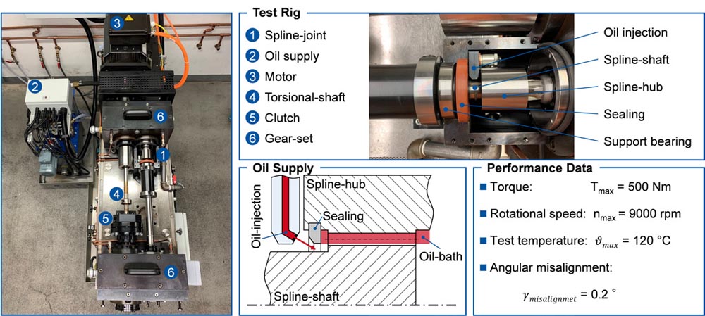
Figure 5—Test-rig setup.
Finally, an additional oil supply was built up to provide a dedicated oil flow rate on a controlled injection temperature for the spline joint. With this extension, the spline joint can be tested under lubricated contact conditions. During operation, the oil is constantly injected into the tooth mesh. An additional sealing, which inner diameter is smaller than the pitch diameter of the spline joint creates an oil bath in the tooth contact and reduces the radial oil flow out of the tooth mesh, see Figure 5. Since the injection temperature of the oil supply is controlled, injection temperatures up to ϑmax = 120°C are realized, which enables application-related testing according to the prevailing lubrication and temperature in the spline-joint contact.
To validate the manufactured shaft misalignment an additional measurement of the bearing seats on a coordinate measuring machine was performed. Despite the distance between the machined bearing seats of l ≈ 600 mm, the precise positioning is shown by the straight line through the measuring points, which reflects the real axis position of the test rig. Additionally considering the alignment of this axis to the axis, which is generated by the already existing bearing seats, the resulting intersection is shown in the diagram. Based on the data, the actual manufactured angular misalignment of the test rig is measured to γmeasure = 0.2006 degrees with an intersection point of the shaft axis that meets in the center of the spline joint, see Figure 6.
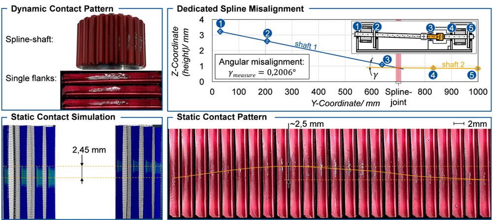
Figure 6—Test-rig validation.
In addition, the test spline-joint design regarding the axial movement of the contact pressure peak was validated during commissioning. A static contact pattern was used for this purpose. Therefore, the clutch of the test rig was locked, and a cyclic torque was applied to the stationary shaft system over a few minutes. Due to this load, the wobble of the flank contacts resulting from the angular misalignment becomes visible in the static contact pattern. The contact distribution, following a sine curve over the circumference, is shown in Figure 6. Compared to the results of the static contact simulation from the design process, it can be seen that the calculation of the contact length with a value of ΔCL,simulation = 2.45 mm agrees with the measured value of ΔCL,measure ≈ 2.5 mm. Continuing, the dynamic contact pattern was recorded to verify the previous measurements of the dedicated shaft misalignment and to validate the generation of the targeted contact conditions. To record the dynamic contact pattern, the spline shaft was painted with contact pattern lacquer before mounting it and rotating the spline joint within moderate torque on the test rig. The dynamic contact pattern shows that the manufactured spline joints and the implemented test rig extension generate a centered contact zone over the spline flanks in operation.
Finally, the test rig commissioning was completed with test runs. The capability of the test rig to provoke wear and fatigue phenomena on misaligned spline joints was shown by the occurrence of tooth flank damage, see Figure 7. Therefore, a first specimen with an as-ground surface finishing has been used. While analyzing the microscopic images of the run tooth flank, the contact zone showed slight changes in the appearance of its surface color. Going further, damage with material removal in the center-right of the contact zone appeared. In the second step, a coated specimen was tested to validate the capability of the test rig setup for the generation of coating wear. Since the different coating layers have different colors, the coating wear was analyzed by its appearance in microscopic images, see Figure 7. For this coating, the MoS2:Ti top layer is visible in silver. For the middle layer, a C:H:Ti layer was used, which can be seen in a black area, where the top layer was removed. Finally, the TiN bottom layer became visible in the golden areas. In the event of a total coating failure, the substrate material became visible underneath the golden layer in a gray hue.
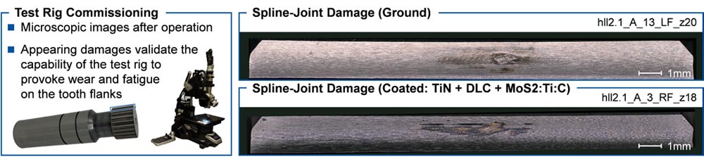
Figure 7—Spline-joint damage.
The occurrence of tooth flank damage validated that the presented test rig in combination with the test spline-joint geometry is sufficient for the testing of wear and fatigue phenomena in misaligned spline joints. Following spline-joint testing and detailed investigations on different surface treatments and optimizations, such as coatings and laser structuring will be performed to raise the load-carrying capacity of crowned spline joints.
Conclusion and Future Work
The state-of-the-art shows that various concepts for the investigation of wear and fatigue phenomena of spline joints exist. For the majority of the existing test rig setups, analogy tests with simple specimens or spline joints are used to generate the contact conditions of loaded spline joints. Especially concerning the contact conditions of rotating misaligned spline joints, the use of analogy test rigs neglects various boundary conditions of the tooth contact. Thus, it becomes apparent that for a comprehensive investigation, component tests with spline joints under realistic operating conditions must be carried out. Cuffaro et al. present such a test rig, which is used for the testing of spline joints under misaligned conditions, whereby the concept is designed for investigations at high torque, lower rotational speed, and low test temperatures (Ref. 13). To investigate misaligned spline joints under high rotational speed, medium torque, and high test temperatures, there is a need for new test concepts.
In the present paper, a spline-joint design and the extension of a back-to-back test rig were presented, which enable the testing of crowned spline-joints under high rotational speed, medium torque, high test temperature, and angular misalignments. For this purpose, the design approach for a spline-joint geometry based on a simulation of the contact conditions with respect to the contact pressure and contact kinematics was presented. Furthermore, the extension of a back-to-back test rig was presented which allows the integration of the designed spline joint into the power circuit of the test rig, while simultaneously enabling test conditions under angular misalignments. Finally, it was shown by the static contact pattern in comparison to the static contact simulation and an additional axis measurement, that the combination of the developed test rig and spline joint is sufficient for the generation of the loads that appear in misaligned spline joints. Therefore, the test rig can be used for spline-joint testing under application-related conditions. Going further, damages that occurred during the test rig commissioning were presented. These damages validate the capability of the test rig to generate wear and fatigue phenomena in misaligned spline joints under high rotational speed, medium torque and high test temperatures.
In the future, spline joints will be tested on the developed test rig to assess wear and fatigue phenomena that arise in misaligned spline joints. The benefits of special surface treatments such as coatings and laser structuring will be evaluated on the presented spline-joint design to demonstrate and validate their potential for industrial applications. Additionally, more spline-joint geometries can be designed to generate different contact conditions on the existing test rig. Therefore, further investigations on the influencing variables on the spline-joint load capacity such as different materials, heat treatments, surface conditions and optimizations, lubrications, test temperatures, or microgeometries can be performed. Throughout these tests, an increase in the power density of spline joints is likely to be enabled and safety margins can be cut due to the availability of extended test data. By achieving this objective, an improvement of the systems can be realized, which ultimately enables the reduction of manufacturing costs and energy consumption of modern aircraft-engine gas turbines.
Acknowledgments
This paper is part of a project that has received funding from the Clean Sky 2 Joint Undertaking under the European Union’s Horizon 2020 research and innovation program under grant agreement No 821344.
In addition, the authors would like to thank the DFG for the funding of an experimental machine (DFG-State Major Instrumentation INST 222/1251-1 FUGG)

References
1.Wink, C. H. and Nakandakar, M. “Influence of Gear Loads on Spline Couplings.” Power Transmission Engineering, Vol. 8, No. 1 (2014): pp. 42–49.
2.Ding, J., McColl, I. R., and Leen, S. B. “The application of fretting wear modelling to a spline coupling.” Wear, Vol. 262, No. 9–10 (2007): pp. 1205–1216. DOI 10.1016/j.wear.2006.11.017.
3.Lechner, Christof and Seume, Jörg. Stationäre Gasturbinen. Springer Vieweg, Berlin (2019).
4.Friedrich, Horst E. and Krishnamoorthy, Sivakumara K. “Leichtbau als Treiber von Innovationen.”. Leichtbau in der Fahrzeugtechnik. Springer Vieweg, Wiesbaden (2017): pp. 1–31.
5.Curà, F., Mura, A., and Ugarte Sevilla, P. Saenz de. “Recent Advances in Spline Couplings Reliability.” Procedia Structural Integrity, Vol. 19 (2019): pp. 328–335. DOI 10.1016/j.prostr.2019.12.036.
6.Laboratory for Machine Tools and Production Engineering (WZL) of RWTH Aachen University, from https://www.wzl.rwth aachen.de/cms/wzl/Forschung/Forschungsumfeld/Forschungsprojekte/Projekte/~dacph/CROSSONT/?lidx=1
7.Limmer, L., Nowell, D., and Hills, D. A. “A combined testing and modelling approach to the prediction of the fretting fatigue performance of splined shafts.” Proceedings of the Institution of Mechanical Engineers, Part G: Journal of Aerospace Engineering, Vol. 215, No. 2 (2001): pp. 105–112. DOI 10.1243/0954410011531808.
8.Ferre, R., Fouvry, S., Berthel, B., Amargier, R., and Ruiz-Sabariego, J. A. “Prediction of the Fretting Fatigue Crack Nucleation Endurance of a Ti-6V-4Al/Ti- 6V-4Al Interface: Influence of Plasticity and Tensile/Shear Fatigue Properties.” Procedia Engineering, Vol. 66 (2013): pp. 803–812. DOI 10.1016/j.proeng.2013.12.134.
9.Leen, S. B., Hyde, T. R., Williams, E. J., Becker, A. A., McColl, I. R., Hyde, T. H., and Taylor, J. W. “Development of a representative test specimen for frictional contact in spline joint couplings.” The Journal of Strain Analysis for Engineering Design, Vol. 35, No. 6 (2000): pp. 521–544. DOI 10.1243/0309324001514279.
10. Hyde, T. R., Leen, S. B., and McColl, I. R. “A simplified fretting test methodology for complex shaft couplings.” Fatigue & Fracture of Engineering Materials & Structures, Vol. 28, No. 11 (2005): pp. 1047–1067. DOI 10.1111/j.1460-2695.2005.00943.x.
11. Wavish, P. M., Houghton, D., Ding, J., Leen, S. B., Williams, E. J., and McColl, I. R. “A multiaxial fretting fatigue test for spline coupling contact.” Fatigue & Fracture of Engineering Materials & Structures, Vol. 32, No. 4 (2009): pp. 325–345. DOI 10.1111/j.1460-2695.2009.01334.x.
12. Ratsimba, C.H.H., McColl, I. R., Williams, E. J., Leen, S. B., and Soh, H. P. “Measurement, analysis and prediction of fretting wear damage in a representative aeroengine spline coupling.” Wear, Vol. 257, No. 11 (2004): pp. 1193–1206. DOI 10.1016/j.wear.2004.08.003.
13. Cuffaro, Vincenzo, Curà, Francesca, and Mura, Andrea. “Test Rig for Spline Couplings Working in Misaligned Conditions.” Journal of Tribology, Vol. 136, No. 1 (2014): p. 2852. DOI 10.1115/1.4025656.
14. Standard ANSI B92.1, 1996. “Involute Splines and Inspection.”
15. Andreas Stephen, Bastian Lenz, Andreas Mehner, and Tim Radel. “Laser structuring of PVD multi-layer systems for wear reduction” Lasers in Manufacturing Conference (2021).
16. Klocke, Fritz and Brecher, Christian. Gear and Transmission Technology: Design—Manufacturing—Investigation—Simulation. Carl Hanser Verlag, München (2017).
17. DIN ISO 14635, 2006. “Gears—FZG test procedures.”
Printed with permission of the copyright holder, the American Gear Manufacturers Association, 1001 N. Fairfax Street, 5th Floor, Alexandria, Virginia 22314. Statements presented in this paper are those of the authors and may not represent the position or opinion of the American Gear Manufacturers Association. |